
DS920+ ,DS1621+ 부트로더 작업 과정
* Asrock J5040 , Debian 11 에서 작업했음.
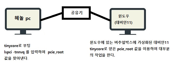
1 ) tinycore로 Asrock J5040 을 부팅해서 "output.dts" 파일의 pcie_root 값을 알아보자.
tc@box:~$ lspci -tnnvq
-[0000:00]-+-00.0 Intel Corporation Gemini Lake Host Bridge [8086:31f0]
+-00.1 Intel Corporation Celeron/Pentium Silver Processor Dynamic Platform and Thermal Framework Processor Participant [8086:318c]
+-02.0 Intel Corporation GeminiLake [UHD Graphics 605] [8086:3184]
+-0e.0 Intel Corporation Celeron/Pentium Silver Processor High Definition Audio [8086:3198]
+-0f.0 Intel Corporation Celeron/Pentium Silver Processor Trusted Execution Engine Interface [8086:319a]
+-12.0 Intel Corporation Celeron/Pentium Silver Processor SATA Controller [8086:31e3]
+-13.0-[01]--+-00.0 Intel Corporation 82575EB Gigabit Network Connection [8086:10a7]
| \-00.1 Intel Corporation 82575EB Gigabit Network Connection [8086:10a7]
+-13.1-[02]----00.0 JMicron Technology Corp. JMB58x AHCI SATA controller [197b:0585]
+-13.2-[03]----00.0 Realtek Semiconductor Co., Ltd. RTL8111/8168/8411 PCI Express Gigabit Ethernet Controller [10ec:8168]
+-13.3-[04]----00.0 ASMedia Technology Inc. ASM1062 Serial ATA Controller [1b21:0612]
+-15.0 Intel Corporation Celeron/Pentium Silver Processor USB 3.0 xHCI Controller [8086:31a8]
+-1f.0 Intel Corporation Celeron/Pentium Silver Processor LPC Controller [8086:31e8]
\-1f.1 Intel Corporation Celeron/Pentium Silver Processor Gaussian Mixture Model [8086:31d4]
tc@box:~$
2 )위의 문장을 보고 SATA controllerr 값을 알아낸 뒤 첨부한 "output.dts" 파일을 수정
pcie_root = "00:12.0"
pcie_root = "00:13.1,00.0"
pcie_root = "00:13.3,00.0"
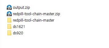
첨부한 "outout.zip" 압축파일을 풀어서 ds1621( DS920 ) 폴더 속에 있는 "output.dts" 파일을 에디터로 아래처럼 수정한다.
( 저의 ASROCK J5040은 SATA 확장카드 포함해서 SATA Controller 3개 이고 각각 2개의 포트가 있음)
pcie_root = "00:12.0";
ata_port = <0x00>;
pcie_root = "00:12.0";
ata_port = <0x01>;
pcie_root = "00:13.1,00.0";
ata_port = <0x00>;
pcie_root = "00:13.1,00.0";
ata_port = <0x01>;
pcie_root = "00:13.3,00.0";
ata_port = <0x00>;
pcie_root = "00:13.3,00.0";
ata_port = <0x01>;
3) 수정된 "output.dts" 파일을 redpill-tool-chain-master 폴더 속에 넣는다.
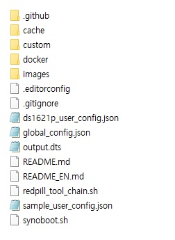
https://github.com/tossp/redpill-tool-chain 에서 다운로드한뒤 압축을 푼다.
redpill-tool-chain-master 폴더 속에 들어 있는 "sample_user_config.json" 파일을 자신의 시스템에 맞게 수정한 후에
이름을 "ds1621p_user_config.json" 로 바꾸어 저장한다.
4) redpill-tool-chain-master 폴더 를 debian 11에 복사해서 넣는다.
5) 아래 절차로 작업을 한다.
sudo apt-get update
sudo apt install docker.io
sudo apt install jq
sudo apt install curl
sudo apt install device-tree-compiler
cd /home/dolbycat/redpill-tool-chain-master
chmod +x redpill_tool_chain.sh
./redpill_tool_chain.sh add https://raw.githubusercontent.com/pocopico/redpill-load/master/redpill-dtb/rpext-index.json
./redpill_tool_chain.sh build ds1621p-7.0.1-42218
./redpill_tool_chain.sh auto ds1621p-7.0.1-42218
dtc -I dts -O dtb output.dts > model_ds1621p.dtb
cp model_ds1621p.dtb ./custom/extensions/redpill-dtb/ds1621p_42661/
./redpill_tool_chain.sh auto ds1621p-7.0.1-42218
6) "images" 폴더에서 첫 번째 "redpill-DS1621+_7.0.1-xxxxxxxx.img" 파일을 삭제하고,
두 번째로 생성된 redpill-DS1621+_7.0.1-xxxxxxxx.img 파일을 사용합니다.
< 참고 >
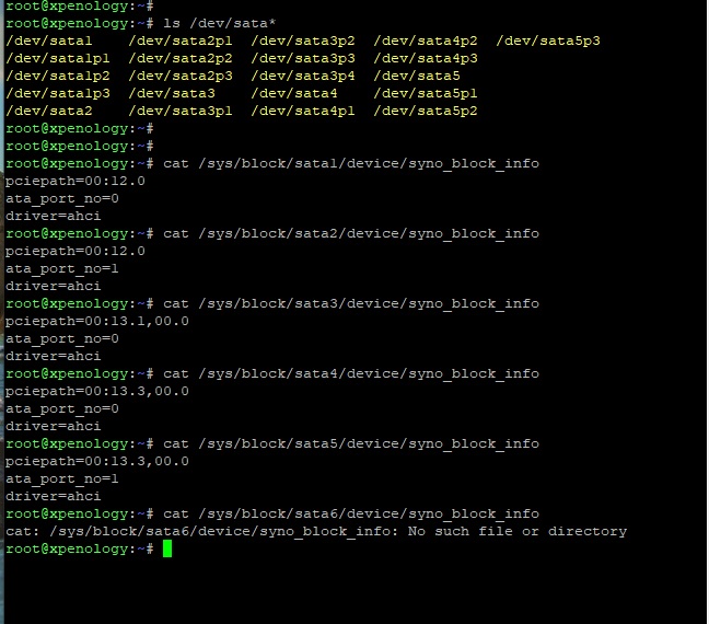
더욱 정확한 pcie_root 값과 ata_port 값은 아래 방식으로 얻을 수있다.
cat /sys/block/sataX/device/syno_block_info
X=1~6
글 밑부분에 자세히 보시면 있습니다. 저도 처음에 어디 올라갔는지 찾았어요.

첨부파일 부분의 가시성이 높이도록 업데이트 되었습니다.
혹 더 변경이 필요해보이는게있으시다면 말씀부탁드립니다!


첨부파일 부분의 가시성이 높이도록 업데이트 되었습니다.
혹 더 변경이 필요해보이는게있으시다면 말씀부탁드립니다!
로더는 tc를 여전히 사용하고, 해당tc에서 pcie값을 알아낸다음 이미지를 빌드해서 시놀설치시 해당이미지를 설치하는건지요? 그렇다면 user_config.json의 sn이나 mac은 어느단계에서 수정하면 될까요
-->수정합니다 본 과정이 부트로더를 만드는과정이고 생성된 img를 rufus를 이용해 usb에 씌운다음에 이걸로 부팅하면 되는건가요 sn이나 mac은 sample_user_config.json을 수정할때 같이 하구요
더불어 데비안이 아닌wsl 우분투에서 해도 될지요
tc는 단순이 나스가 될 컴의 pcie_root값을 알아내기 위한것 뿐입니다.
tc로 부팅후 lspci -tnnvq 명령어를 넣으면 컴의 pci값을 볼수있으니깐요.
실제 컴파일은 데비안 상에서 redpill-tool-chain-master로 합니다.
우분투에서는 해보지 않아서 모르지만 화정큐삼님한테 문의 하시면 답을 얻을수있을 것입니다.
저도 우분투는 네이티브로만 작업해 봤습니다.
WSL VM 우분투에선 툴체인 사용시 이슈가 있었다고 tossp님 깃헙에 몇번 올라왔었는데요.
관련 링크 드려 봅니다.
tossp님이 중국인이라서 크롬에서 중국어 번역으로 확인해 보시기 바랍니다.
https://github.com/tossp/redpill-tool-chain/issues/62
./redpill_tool_chain.sh add https://github.com/jumkey/redpill-load/raw/develop/redpill-dtb/rpext-index.json
Downloading
################################################################################################################# 100.0% -=O=- # # ## -=O=- # ### -=O=- #### -=O=- # ## -=O=- # # ## -=O=- # # # # -=O=- # # ## -=O=- # ### -=O=- #### -=O=- # ## -=O=- # # ## -=O=- # # # # -=O=- # # ## -=O=- # ### -=O=- #### -=O=- # ## -=O=- # # ## -=O=- # # # #curl: (28) Connection timed out after 300001 milliseconds
이 부분에서 time out나는데 이게 말씀하신 그 문제일까요
==============================================================
다시 했더니 잘되네요 희한하네요
./redpill_tool_chain.sh add https://github.com/jumkey/redpill-load/raw/develop/redpill-dtb/rpext-index.json
Downloading
################################################################################################################# 100.0%################################################################################################################# 100.0%
jumkey.dtb
Name: jumkey.dtb
Description: Create your own device tree binary
Support platform: ds1621p_42218 ds2422p_42218 ds920p_42218 ds920p_42550
Installation is complete!
혹시 16개의 cpu (8c16t)와 hw트랜스코딩이 가능하면서 본방법 적용가능한 모델이 있을까요
아직은 없는 것으로 알고 있습니다. 헤놀포럼에서 IG-88님이 연구중인데 좀 기다려야될것 같아요.
혹시 ./redpill_tool_chain.sh add https://github.com/jumkey/redpill-load/raw/develop/redpill-dtb/rpext-index.json 이 명령어를 반드시 사용할 NAS에서 실행해야 하는지요?
현재 빌드를 NAS가 아닌 다른 데스크탑에서, 저 명령어를 돌리고 있는데 문제가 될까요
또한 다들 DS920+ 시리얼은 어떻게 하셨는지요 가지고 있는 918+시리얼을 넣으면 될까요
원래 다른 pc에서 합니다. 나스pc에서는 tc로 pcie_root값만 얻어내고 나머지 작업은 전부 다른 pc에서 합니다.
저의 경우 윈도우10에깔린 버추얼박스속 데비안11에서 작업했어요.
시리얼은 아마 918것을 넣어도 될것입니다.920에서는 트랜스코딩조 될것입니다.
혹시 lspci -tnnvq를 여기 달아주시면 제가 빌드해드리죠.
감사합니다 핫포사이님,
./redpill_tool_chain.sh auto ds920p-7.0.1-42218 입력시
마지막에 checksum 에러나는데 혹시 이게 어디 저장된 pat cache파일을 지울수 있을런지요
[#] Verifying /opt/redpill-load/cache/ds920p_42218.pat file... [ERR]
[!] Checksum mismatch - expected 73053911bd118b432d5a2036dc62d518eed83b78b32c1eb23696d59725a14892 but computed e4909de1d9954b7ad610cc6c741a6e9a2166c49c5d7ad2dd4acda6c2956533fa
*** Process will exit ***
cache폴더 안에 들어있어요. 미리 넣어두어도 됩니다.
핫포사이님 안녕하세요.
올려주신 DS920용 output.dts 파일 보면 internal_slot@1~internal_slot@6까지 sata 가 보이는데 제 NAS 시스템을 lspci -tnnvq 했을 때 아래와 같이 나옵니다.
-[0000:00]-+-00.0 Intel Corporation 4th Gen Core Processor DRAM Controller [8086:0c00]
+-02.0 Intel Corporation Xeon E3-1200 v3/4th Gen Core Processor Integrated Graphics Controller [8086: 0412]
+-03.0 Intel Corporation Xeon E3-1200 v3/4th Gen Core Processor HD Audio Controller [8086:0c0c]
+-14.0 Intel Corporation 9 Series Chipset Family USB xHCI Controller [8086:8cb1]
+-16.0 Intel Corporation 9 Series Chipset Family ME Interface #1 [8086:8cba]
+-1a.0 Intel Corporation 9 Series Chipset Family USB EHCI Controller #2 [8086:8cad]
+-1b.0 Intel Corporation 9 Series Chipset Family HD Audio Controller [8086:8ca0]
+-1c.0-[01]--
+-1c.2-[02]----00.0 Realtek Semiconductor Co., Ltd. RTL8111/8168/8411 PCI Express Gigabit Ethernet Co ntroller [10ec:8168]
+-1c.3-[03-04]----00.0-[04]--
+-1d.0 Intel Corporation 9 Series Chipset Family USB EHCI Controller #1 [8086:8ca6]
+-1f.0 Intel Corporation 9 Series Chipset Family H97 Controller [8086:8cc6]
+-1f.2 Intel Corporation 9 Series Chipset Family SATA Controller [AHCI Mode] [8086:8c82]
\-1f.3 Intel Corporation 9 Series Chipset Family SMBus Controller [8086:8ca2]
이럴 경우 output.dts 파일을 어떻게 수정해야 하나요? ^^;;
+-1f.2 Intel Corporation 9 Series Chipset Family SATA Controller [AHCI Mode] [8086:8c82]
pcie_root = "00:1f.2" 입니다. 보드 명칭이 어떻게되고 sata포트는 몇개인가요?
네 감사합니다.
메인보드는 GA-H97M-HD3 보드이고, 온보드 sata포트는 6개입니다.
internal_slot@1 {
protocol_type = "sata";
power_pin_gpio = <0x14 0x00>;
detect_pin_gpio = <0x23 0x01>;
led_type = "lp3943";
ahci {
pcie_root = "00:1f.2";
ata_port = <0x00>;
};
led_green {
led_name = "syno_led0";
};
led_orange {
led_name = "syno_led1";
};
};
internal_slot@2 {
protocol_type = "sata";
power_pin_gpio = <0x15 0x00>;
detect_pin_gpio = <0x24 0x01>;
led_type = "lp3943";
ahci {
pcie_root = "00:1f.2";
ata_port = <0x01>;
};
led_green {
led_name = "syno_led2";
};
led_orange {
led_name = "syno_led3";
};
};
internal_slot@3 {
protocol_type = "sata";
power_pin_gpio = <0x16 0x00>;
detect_pin_gpio = <0x25 0x01>;
led_type = "lp3943";
ahci {
pcie_root = "00:1f.2";
ata_port = <0x00>;
};
led_green {
led_name = "syno_led4";
};
led_orange {
led_name = "syno_led5";
};
};
internal_slot@4 {
protocol_type = "sata";
power_pin_gpio = <0x17 0x00>;
detect_pin_gpio = <0x26 0x01>;
led_type = "lp3943";
ahci {
pcie_root = "00:1f.2";
ata_port = <0x01>;
};
led_green {
led_name = "syno_led6";
};
led_orange {
led_name = "syno_led7";
};
};
internal_slot@5 {
protocol_type = "sata";
power_pin_gpio = <0x18 0x00>;
detect_pin_gpio = <0x27 0x01>;
led_type = "lp3943";
ahci {
pcie_root = "00:1f.2";
ata_port = <0x00>;
};
led_green {
led_name = "syno_led8";
};
led_orange {
led_name = "syno_led9";
};
};
internal_slot@6 {
protocol_type = "sata";
power_pin_gpio = <0x19 0x00>;
detect_pin_gpio = <0x28 0x01>;
led_type = "lp3943";
ahci {
pcie_root = "00:1f.2";
ata_port = <0x01>;
};
led_green {
led_name = "syno_led10";
};
led_orange {
led_name = "syno_led11";
};
};
이렇게 수정하는게 맞나요?
sata칩이 1개인거 같은데 ata_port 값이 중첩됩니다. 0x00 ~ 0x05 로 수정하세요.
위의 값은 sata칩이 3개이고 포트가 각각 2개일때 하는것입니다.
아.. 이제 이해 했습니다.
핫포사이님 말씀대로 해서 테스트 해보겠습니다.
감사합니다.
cmt alert


